- 您现在的位置:买卖IC网 > Sheet目录1993 > DS12CR887-5+ (Maxim Integrated Products)IC RTC W/RAM 128 BYTE 24-EDIP
DS12R885/DS12CR887/DS12R887
RTCs with Constant-Voltage Trickle Charger
14
Maxim Integrated
methods of avoiding any possible incorrect time and
calendar reads are covered later in this text.
The three alarm bytes can be used in two ways. First,
when the alarm time is written in the appropriate hours,
minutes, and seconds alarm locations, the alarm inter-
rupt is initiated at the specified time each day, if the
alarm-enable bit is high. In this mode, the “0” bits in the
alarm registers and the corresponding time registers
must always be written to 0 (Table 2A and 2B). Writing
the 0 bits in the alarm and/or time registers to 1 can
result in undefined operation.
The second use condition is to insert a “don’t care”
state in one or more of the three alarm bytes. The don’t-
care code is any hexadecimal value from C0 to FF. The
two most significant bits of each byte set the don’t-care
condition when at logic 1. An alarm is generated each
hour when the don’t-care bits are set in the hours byte.
Similarly, an alarm is generated every minute with
don’t-care codes in the hours and minute alarm bytes.
The don’t-care codes in all three alarm bytes create an
interrupt every second.
All 128 bytes can be directly written or read, except for
the following:
1) Registers C and D are read-only.
2) Bit 7 of register A is read-only.
3) The MSB of the seconds byte is read-only.
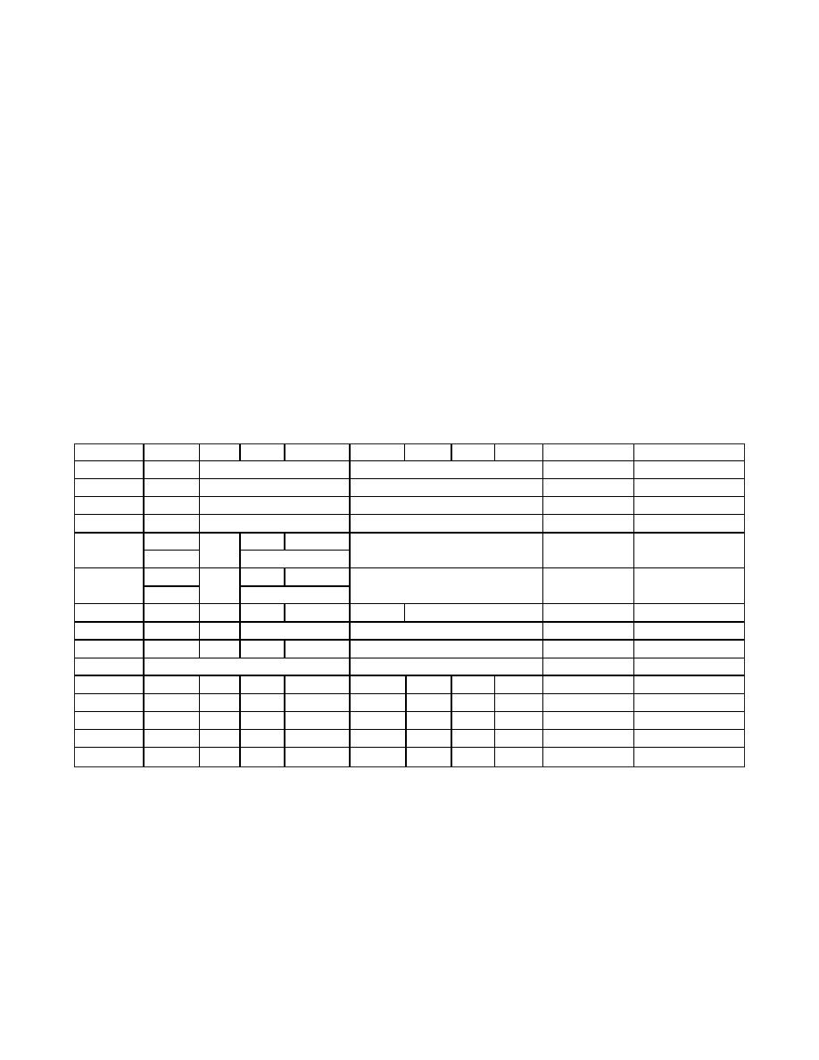
Table 2A. Time, Calendar, and Alarm Data Modes—BCD Mode (DM = 0)
ADDRESS
BIT 7
BIT 6
BIT 5
BIT 4
BIT 3
BIT 2
BIT 1
BIT 0
FUNCTION
RANGE
00H
0
10 Seconds
Seconds
00–59
01H
0
10 Seconds
Seconds
Seconds Alarm
00–59
02H
0
10 Minutes
Minutes
00–59
03H
0
10 Minutes
Minutes
Minutes Alarm
00–59
AM/PM
0
10 Hours
04H
0
10 Hours
Hours
1–12 +AM/PM
00–23
AM/PM
0
10 Hours
05H
0
10 Hours
Hours
Hours Alarm
1–12 +AM/PM
00–23
06H
0
Day
01–07
07H
0
10 Date
Date
01–31
08H
0
10 Months
Month
01–12
09H
10 Years
Year
00–99
0AH
UIP
DV2
DV1
DV0
RS3
RS2
RS1
RS0
Control
—
0BH
SET
PIE
AIE
UIE
SQWE
DM
24/12
DSE
Control
—
0CH
IRQF
PF
AF
UF
0
Control
—
0DH
VRT
0
Control
—
0EH-7F
X
RAM
—
X = Read/Write Bit.
Note: Unless otherwise specified, the state of the registers is not defined when power is first applied. Except for the seconds regis-
ter, 0 bits in the time and date registers can be written to 1, but may be modified when the clock updates. 0 bits should always be
written to 0 except for alarm mask bits.
发布紧急采购,3分钟左右您将得到回复。
相关PDF资料
DS1302SN-16
IC TIMEKEEPER T-CHRG IND 16-SOIC
DS1305E/T&R
IC RTC SERIAL ALARM 20-TSSOP
DS1306EN/T&R
IC RTC SERIAL ALARM IND 20-TSSOP
DS1307N
IC RTC SERIAL 512K IND 8-DIP
DS1308U-3+
IC RTC 56BYTE NVRAM I2C 8UMAX
DS1315EN-5/T&R
IC TIME CHIP PHANTOM 20-TSSOP
DS1318E+
IC COUNTER ELAPSED TIME 24-TSSOP
DS1337S+C01
IC RTC SERIAL 2WIRE LP 8-SOIC
相关代理商/技术参数
DS12R885-33
制造商:Maxim Integrated Products 功能描述:REAL TIME CLOCK MULTIPLEXED 114BYTE - Bulk
DS12R885-5
制造商:Maxim Integrated Products 功能描述:REAL TIME CLOCK MULTIPLEXED 114BYTE - Bulk
DS12R885S-33
制造商:Rochester Electronics LLC 功能描述: 制造商:Maxim Integrated Products 功能描述:
DS12R885S-33/T&R
制造商:Maxim Integrated Products 功能描述:REAL TIME CLOCK MULTIPLEXED 114BYTE 24SOIC W - Tape and Reel
DS12R885S-33+
功能描述:实时时钟 RTC w/Constant V Trickle Charger RoHS:否 制造商:Microchip Technology 功能:Clock, Calendar. Alarm RTC 总线接口:I2C 日期格式:DW:DM:M:Y 时间格式:HH:MM:SS RTC 存储容量:64 B 电源电压-最大:5.5 V 电源电压-最小:1.8 V 最大工作温度:+ 85 C 最小工作温度: 安装风格:Through Hole 封装 / 箱体:PDIP-8 封装:Tube
DS12R885S-33+T&R
制造商:Maxim Integrated Products 功能描述:REAL TIME CLOCK MULTIPLEXED 114BYTE - Tape and Reel 制造商:Maxim Integrated Products 功能描述:IC RTC W/RAM 128 BYTE 24-SOIC
DS12R885S-33+T&R
功能描述:实时时钟 RTC w/Constant V Trickle Charger RoHS:否 制造商:Microchip Technology 功能:Clock, Calendar. Alarm RTC 总线接口:I2C 日期格式:DW:DM:M:Y 时间格式:HH:MM:SS RTC 存储容量:64 B 电源电压-最大:5.5 V 电源电压-最小:1.8 V 最大工作温度:+ 85 C 最小工作温度: 安装风格:Through Hole 封装 / 箱体:PDIP-8 封装:Tube
DS12R885S-5
制造商:Maxim Integrated Products 功能描述:REAL TIME CLOCK MULTIPLEXED 114BYTE 24SOIC W - Bulk